Airtightness concept


Airtightness
concept
Airtightness is required by law in Germany. The German Energy Saving Ordinance (EnEV), which stipulates minimum requirements regarding energy use in new and renovated buildings, and the standard DIN 4108 Parts 2 and 3 on thermal protection both require permanently airtight building envelopes. The reason for this is simple: thermally insulated buildings must be built in an airtight manner if they are to be energy-efficient, deliver sufficient comfort levels and also provide protection against moisture damage. pro clima offers an all-round system for this purpose, with solutions for flat surfaces, joints, adhesive bonds and detail features. In addition, installation technicians and architects can benefit from a comprehensive range of services, including our Technical Support, testing of building structures, building-physics assessments and on-site training.


Airtightness starts at the planning stage
Careful planning of airtightness is of critical importance. After all, this planning is the prerequisite for implementing a high-quality airtight building envelope in a cost-effective and unproblematic manner on your building project. To achieve this goal, the work of all participating trades must be coordinated before and during on-site installation. This is stipulated by DIN 4108-7, which deals with requirements, recommendations and examples for planning and performance with regard to airtightness. An airtightness concept is required when planning an airtight building envelope.

How much detail is necessary in an airtightness concept?
The German Trade Association for Airtightness in Construction (FLiB) has specified that an airtightness concept should include all measures that affect the planning, implementation and subsequent checking of an airtightness building envelope. These measures include:
- The initial design concept
- Detailed planning
- Requests for quotations / tenders
- Coordination meeting for all trades
- Implementation of airtightness sealing work
- Quality control
What should an initial airtightness design concept contain, and how should it be prepared?
In practice, the initial design concept is often regarded merely as a preliminary planning stage for the full airtightness concept. However, all of the steps identified above are necessary in order to create an airtight building envelope in a professional and reliable manner. Detailed execution planning for airtight joint features is particularly important in this regard. Financial support programmes for energy-efficient refurbishment or new-build projects, such as those offered by the Reconstruction Loan Corporation (KfW) in Germany, generally demand an airtightness concept as part of the required technical documentation. An initial design concept is generally sufficient for this purpose. The relevant information for each support programme will provide a detailed description of the requirements. We would like to consider initial airtightness design concepts in further detail here.
1. Summary of general information
An initial design concept will summarise the most important general information relating to the construction project. This will include the location, construction method, financial support programmes and their aims, details of building services technology, etc.
2. Drawing of the general course of the airtightness layer
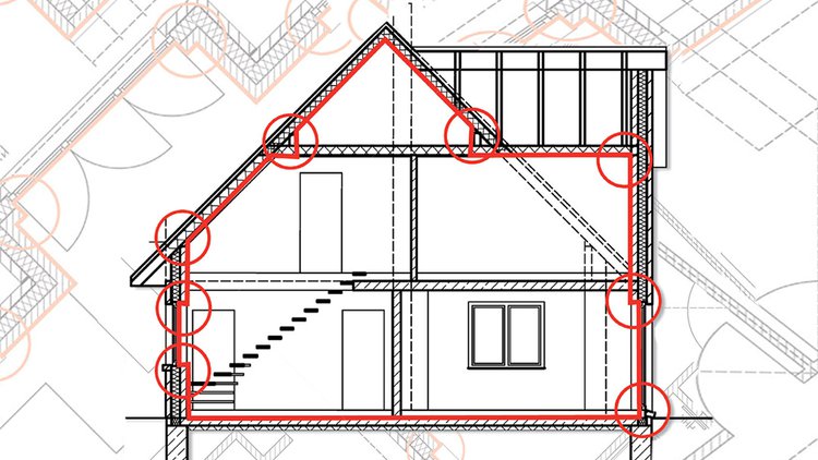
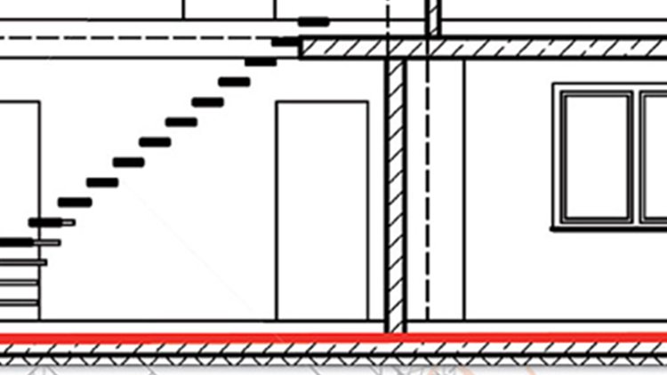
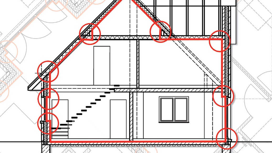
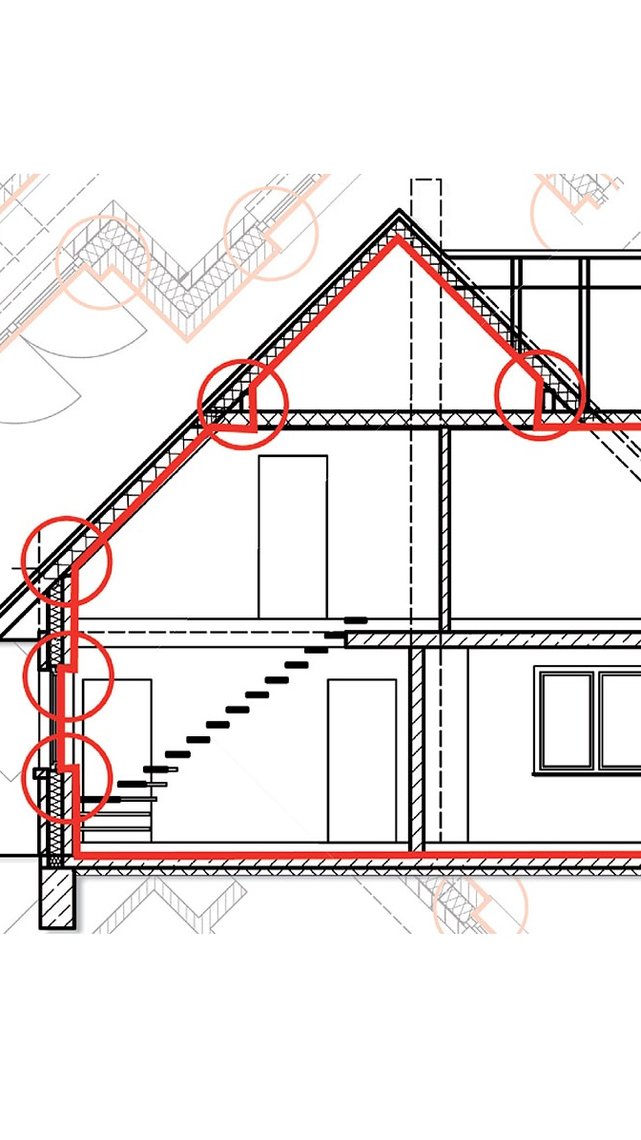
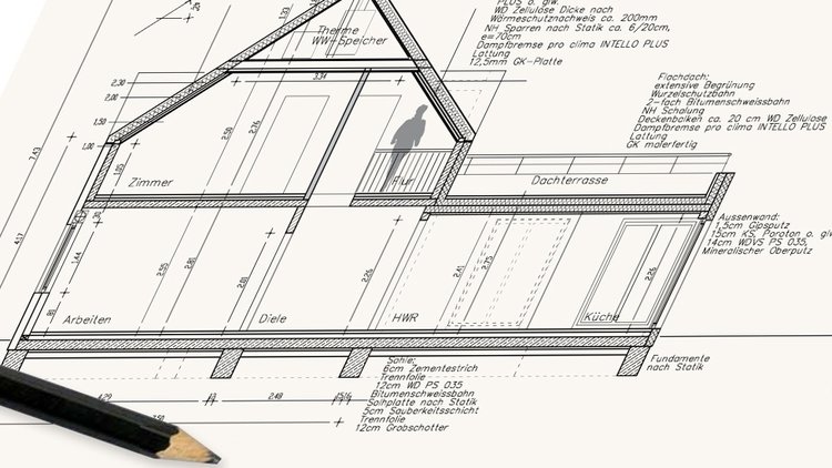
As an initial planning step, the general course of the airtight building envelope is specified and included in cross-section and floor-plan drawings for the building. The airtight building envelope should ideally fully enclose the heated volume of the finished building.
3. Specification of airtightness in standard structures
The next step is to define the standard structure of all relevant components of the building envelope, such as the roof, exterior walls, basement ceiling, etc. This specifies precisely which structure layer will perform the airtightness function for surfaces. This could be the reinforced concrete slab in the case of a basement ceiling, or the interior plasterwork for exterior walls. This should be documented in the form of a table, as a detailed written description, or as labelling on cross-section and floor-plan drawings.
4. Specification of the course of airtightness sealing and marking of detail features
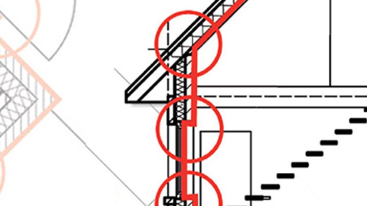
The airtightness layers are marked and highlighted with a coloured line for each element in cross-section and floor-plan drawings. Any joint details that arise – e.g. at transitions between building elements, penetrations or other joints – are marked with a coloured circle. As a check, it must be possible to trace along the airtight building envelope with a pen without having to lift the pen (i.e. no gaps or jumps). This is the so-called “pen test”.
5. Sketching of the air sealing at detail features
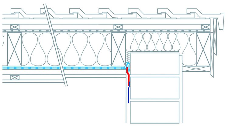
In this step, the marked joint details are shown in a rough manner in simplified sketches and general instructions are provided. A very simple, schematic illustration is sufficient for the initial design concept. It is not necessary to carry out detailed construction planning for the various trades. Hand-drawn sketches or construction site photos may be used here, for example. The aim is to draw attention to critical points – e.g. that the entire surface of masonry walls behind stud-wall installations needs to be plastered. Detailed construction planning is not necessary when preparing an initial airtightness design concept, but is instead the responsibility of the relevant planner.
Planning right through to detail level
The initial airtightness design concept is not a substitute for detailed construction planning. This should be stated explicitly as part of the initial design concept. However, construction planning for the various trades should be carried out as a subsequent step as part of successful project implementation. It should be decided in advance who is responsible for construction planning. This will generally be the specialist planner or the architect. If a planner has not been appointed – in the case of partial refurbishment projects for example – or if sufficient trade planning has not been carried out, the executing tradesperson (knowingly or unknowlingly) often effectively makes planning decisions with corresponding consequences with regard to liability. In situations of this kind, appropriate insurance coverage should be obtained or comprehensive planning information should be requested that describes the relevant work in sufficient detail.
Airtightness sealing in practice
Basic principles, implementation and checking
pro clima airtightness systems
pro clima provides coordinated system solutions for practical installation of permanently reliable airtightness – these systems each consist of a vapour control (alternate terms: vapour check or retarder) and airtightness membrane, a joint adhesive, an adhesive tape, and grommets/gaskets and solutions for detail features.
- Complete system with coordinated individual products
- 10-year system warranty
- Best possible protection against mould and damage to structures thanks to intelligent diffusion adaptation
- Passive House-certified systems
- Adhesive tapes with adhesion for 100 years, independently tested and confirmed
- Healthier buildings thanks to excellent values in hazardous substance testing


